RIM KNOWLEDGE
When developing carbon rims, the most important thing is to achieve the balancing act between optimum stiffness and flexibility. Of course, a carbon rim needs to be light, but it also has to be strong enough to ensure that you can enjoy it for a long time.
Like our other components, all our rims are simulated using the finite element method. This allows us to sound out the properties required for the respective rim types in order to best meet these requirements from the very start of the development phase. We produce carbon rims that are up to 30% more robust than our competitors at similar weight. This is particularly evident in the enduro and downhill sector, where weight alone is no longer the sole criterion and robustness plays a decisive role.
If you take a closer look at the variety of carbon rims, you’ll notice a range of unusual names for technologies, systems and concepts. They sound interesting, but they are rarely explained, and nobody really understands them. We want to change this situation, because we believe that it really only comes down to a few engineering basics. Here’s an insight into the areas that we think really matter:
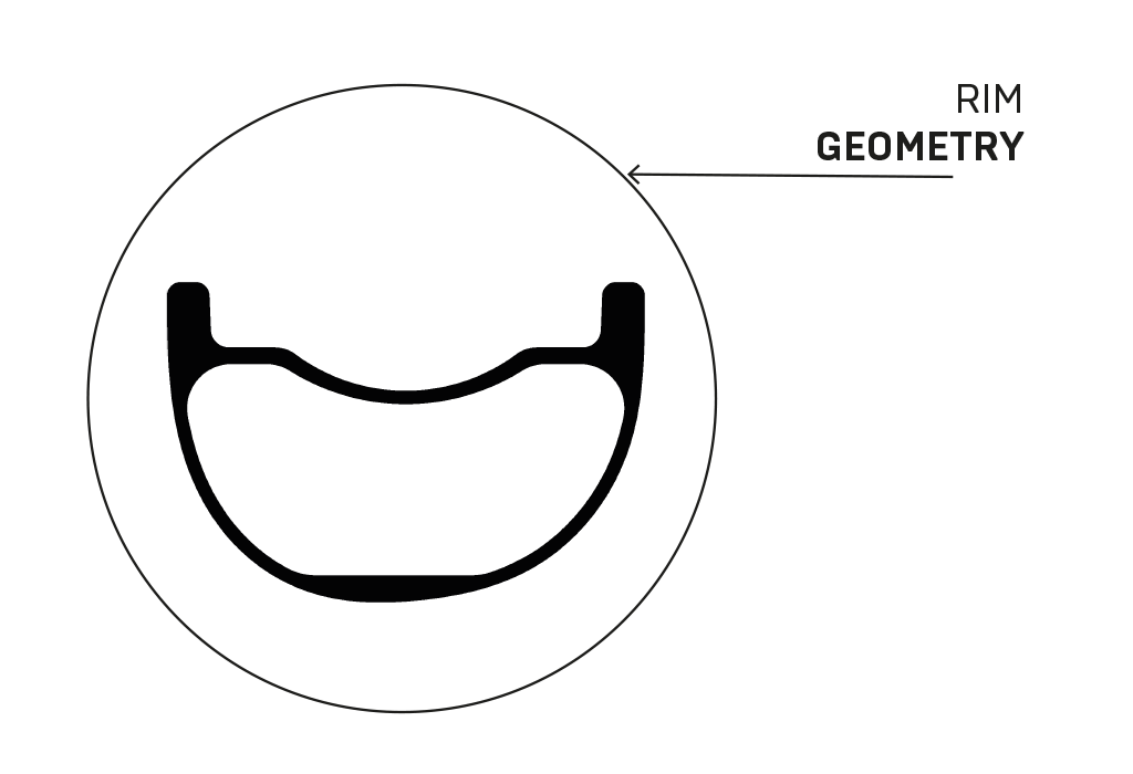
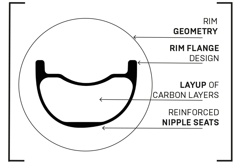
RIM GEOMETRY
Geometric effect has a huge influence on impact behaviour and is often ignored by our competitors. From a round U-shape to a sharp V-shape there are many gradations, each of which has certain advantages and disadvantages. All our rims have been designed in such a way that they have a geometry that is appropriate to the load in their respective area of application. This saves weight and provides robustness where it is needed.
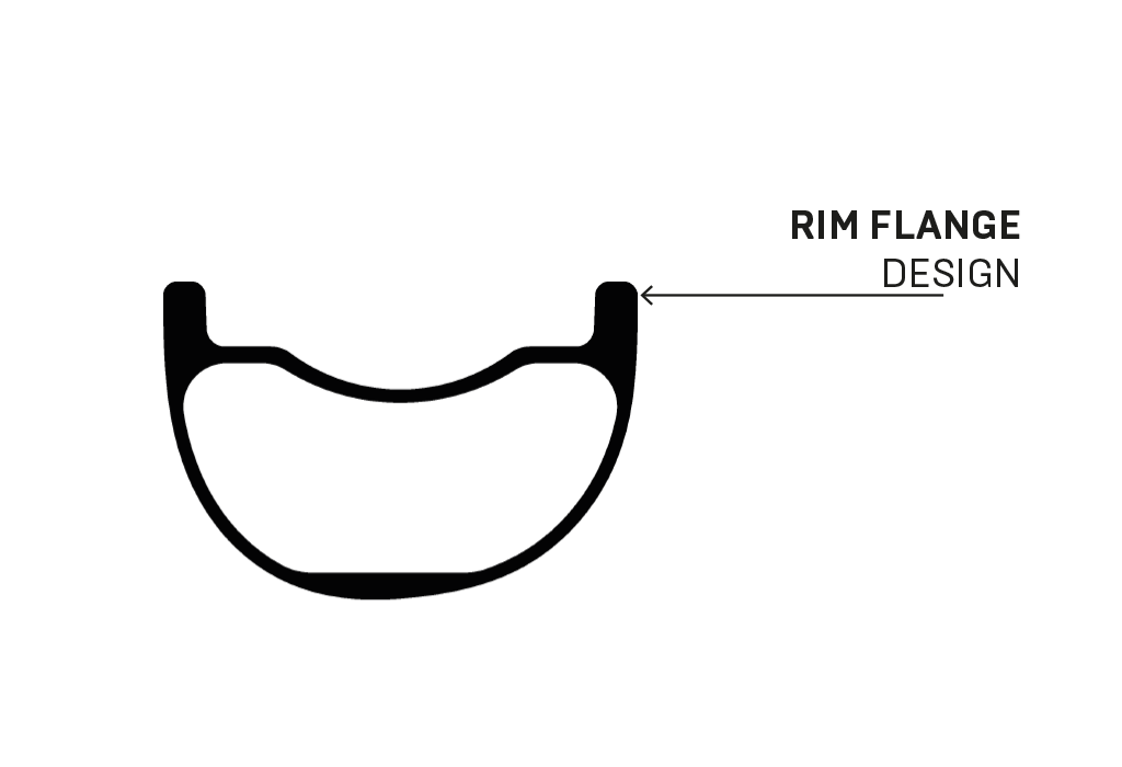
RIM FLANGE DESIGN
Bikers are riding at increasingly lower tyre pressures to improve grip off-road. This is also causing an increased number of “snakebite” or “pinch” punctures on the rim and the rim flange is sometimes subjected to extreme impact. The geometry and material behaviour of the rim flange must be designed for the type of application if it is to absorb a large proportion of the impact and guarantee benign failure in the event of a puncture.
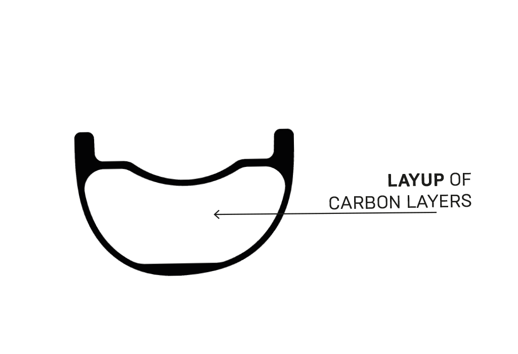
LAYUP OF CARBON LAYERS
The layup is defined by the type of material used and the number and fibre orientation of the layers. The basic principle is that material is used where it is needed. Using a lot doesn’t always help a lot. Selective use of material can influence not only the robustness but also the deformation behaviour, i.e. the flexibility of the rim. Here too, our point of orientation is the respective area of application for the rim.
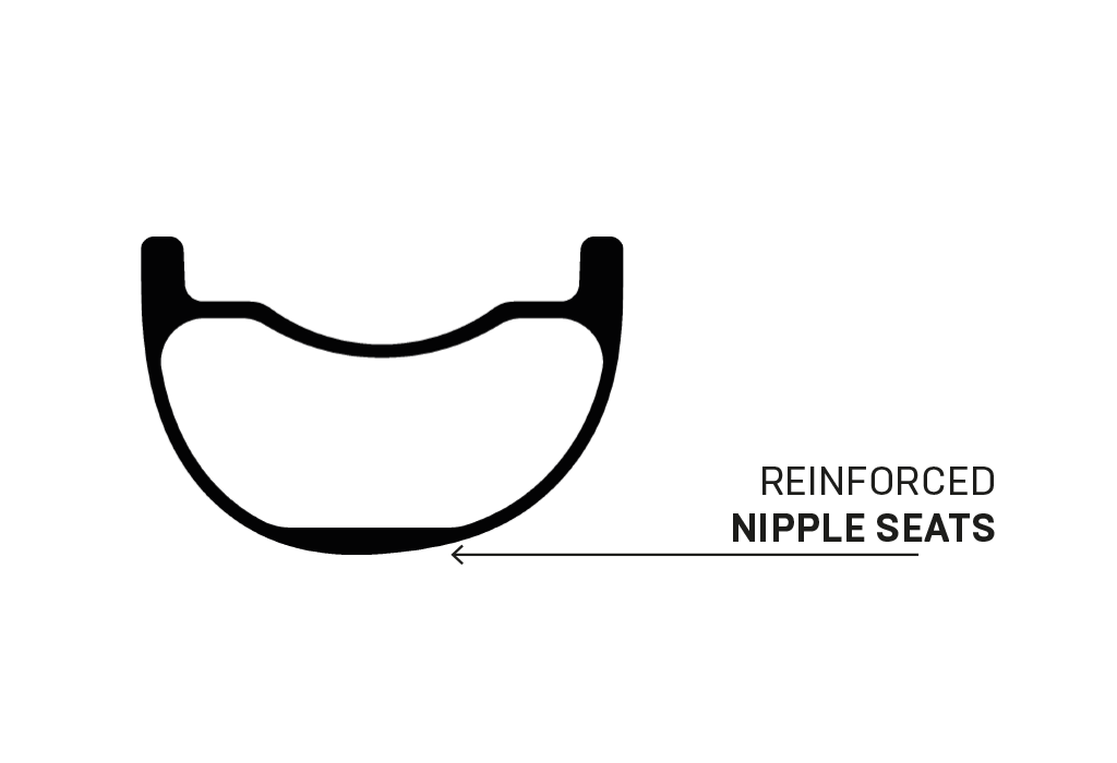
REINFORCED NIPPLE SEATS
The laminate in the area around the nipple seat is locally reinforced, so that in the event of significant overloading, a spoke breakage occurs rather than a spoke pull-through, which would damage the rim laminate. Although replacing a spoke may be tiresome, it’s not nearly as expensive as replacing a rim. The spoke holes and the valve holearemilled rather than drilled. This puts less stress on the material and prevents the layers delaminating from one another. We also ensure that the spoke holes are directionally milled and asymmetrically arranged for even distribution of spoke tension. This avoids uneven loading of the spokes. Any uneven load on the spokes is transferred to the rim and has an adverse effect. The milling and layout also make it easy to embed the nipples at the correct angle.
COORDINATED DIMENSIONING
Logical coordination of these individual profile areas with one another (always taking into account the respective application area of the rim) is essential. No area should be too large. An exaggerated layup of the rim body does not help durability if the rim flanges are not designed for the same purpose. What’s the use of a super-stiff rim if the rim flange breaks the first time you get a pinch puncture? You also don’t need to design a road bike rim so that you can ride it on trails. That’s what gravel rims are for.
In short, designing and manufacturing a rim requires a holistic, systematic approach.